Eaton 255895
SKU: CS5021039MPN: 255895UPC/EAN: 04015082558956
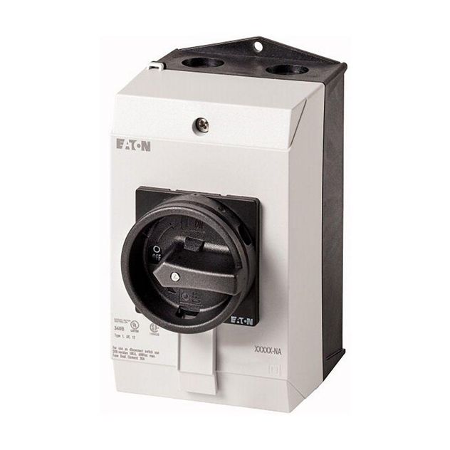
Eaton Moeller® series P1 Main switch


$433.61
UnitAvailable on backorder
Product Details
Eaton Moeller® series P1 Main switch, P1, 32 A, surface mounting, 3 pole, 1 N/O, 1 N/C, STOP function, With black rotary handle and locking ring, UL/CSA
Attributes
| 10 10 Temperature Rise | The panel builder is responsible for the temperature rise calculation. Eaton will provide heat dissipation data for the devices. |
| 10 11 Short Circuit Rating | Is the panel builder’s responsibility. The specifications for the switchgear must be observed. |
| 10 12 Electromagnetic Compatibility | Is the panel builder’s responsibility. The specifications for the switchgear must be observed. |
| 10 13 Mechanical Function | The device meets the requirements, provided the information in the instruction leaflet (IL) is observed. |
| 10 2 2 Corrosion Resistance | Meets the product standard’s requirements. |
| 10 2 3 1 Verification Of Thermal Stability Of Enclosures | Meets the product standard’s requirements. |
| 10 2 3 2 Verification Of Resistance Of Insulating Materials To Normal Heat | Meets the product standard’s requirements. |
| 10 2 3 3 Resist Of Insul Mat To Abnormal Heat Fire By Internal Elect Effects | Meets the product standard’s requirements. |
| 10 2 4 Resistance To Ultra Violet Uv Radiation | UV resistance only in connection with protective shield. |
| 10 2 5 Lifting | Does not apply, since the entire switchgear needs to be evaluated. |
| 10 2 6 Mechanical Impact | Does not apply, since the entire switchgear needs to be evaluated. |
| 10 2 7 Inscriptions | Meets the product standard’s requirements. |
| 10 3 Degree Of Protection Of Assemblies | Does not apply, since the entire switchgear needs to be evaluated. |
| 10 4 Clearances And Creepage Distances | Meets the product standard’s requirements. |
| 10 5 Protection Against Electric Shock | Does not apply, since the entire switchgear needs to be evaluated. |
| 10 6 Incorporation Of Switching Devices And Components | Does not apply, since the entire switchgear needs to be evaluated. |
| 10 7 Internal Electrical Circuits And Connections | Is the panel builder’s responsibility. |
| 10 8 Connections For External Conductors | Is the panel builder’s responsibility. |
| 10 9 2 Power Frequency Electric Strength | Is the panel builder’s responsibility. |
| 10 9 3 Impulse Withstand Voltage | Is the panel builder’s responsibility. |
| 10 9 4 Testing Of Enclosures Made Of Insulating Material | Is the panel builder’s responsibility. |
| Accessories | Auxiliary contact or neutral conductor fitted by user. |
| Actuator Color | Black |
| Actuator Type | Door coupling rotary drive |
| Ambient Operating Temperature Enclosed Max | 40 CEL |
| Ambient Operating Temperature Enclosed Max Uom | CEL |
| Ambient Operating Temperature Enclosed Min | -25 CEL |
| Ambient Operating Temperature Enclosed Min Uom | CEL |
| Ambient Operating Temperature Max | 40 CEL |
| Ambient Operating Temperature Max Uom | CEL |
| Ambient Operating Temperature Min | -25 CEL |
| Ambient Operating Temperature Min Uom | CEL |
| Assigned Motor Power At 115 120 V 60 Hz 1 Phase | 1 A25 |
| Assigned Motor Power At 115 120 V 60 Hz 1 Phase Uom | A25 |
| Assigned Motor Power At 200 208 V 60 Hz 1 Phase | 2 A25 |
| Assigned Motor Power At 200 208 V 60 Hz 1 Phase Uom | A25 |
| Assigned Motor Power At 200 208 V 60 Hz 3 Phase | 3 A25 |
| Assigned Motor Power At 200 208 V 60 Hz 3 Phase Uom | A25 |
| Assigned Motor Power At 230 240 V 60 Hz 1 Phase | 3 A25 |
| Assigned Motor Power At 230 240 V 60 Hz 1 Phase Uom | A25 |
| Assigned Motor Power At 230 240 V 60 Hz 3 Phase | 7.5 A25 |
| Assigned Motor Power At 230 240 V 60 Hz 3 Phase Uom | A25 |
| Assigned Motor Power At 460 480 V 60 Hz 3 Phase | 10 A25 |
| Assigned Motor Power At 460 480 V 60 Hz 3 Phase Uom | A25 |
| Assigned Motor Power At 575 600 V 60 Hz 3 Phase | 15 A25 |
| Assigned Motor Power At 575 600 V 60 Hz 3 Phase Uom | A25 |
| Climatic Proofing | Damp heat, cyclic, to IEC 60068-2-30 Damp heat, constant, to IEC 60068-2-78 |
| Control Circuit Reliability | 1 failure per 100,000 switching operations statistically determined, at 24 V DC, 10 mA) |
| Degree Of Protection | NEMA 12 |
| Degree Of Protection Front Side | IP65 |
| Device Construction | Complete device in housing |
| Electrical Connection Type Of Main Circuit | Screw connection |
| Equipment Heat Dissipation Current Dependent Pvid | 1.8 WTT |
| Equipment Heat Dissipation Current Dependent Pvid Uom | WTT |
| Features | Version as main switch Version as maintenance-/service switch |
| Fitted With | Black rotary handle and locking ring |
| Functions | STOP function Interlockable |
| Heat Dissipation Capacity Pdiss | 0 WTT |
| Heat Dissipation Capacity Pdiss Uom | WTT |
| Heat Dissipation Per Pole Current Dependent Pvid | 1.8 WTT |
| Heat Dissipation Per Pole Current Dependent Pvid Uom | WTT |
| Lifespan Mechanical | 300,000 Operations |
| Load Rating | 1.3 x Iₑ (with intermittent operation class 12, 60 % duty factor) 1.6 x Iₑ (with intermittent operation class 12, 40 % duty factor) 2 x Iₑ (with intermittent operation class 12, 25 % duty factor) |
| Mounting Method | Surface mounting |
| Mounting Position | As required |
| Number Of Auxiliary Contacts Change Over Contacts | 0.0000 |
| Number Of Auxiliary Contacts Normally Closed Contacts | 1.0000 |
| Number Of Auxiliary Contacts Normally Open Contacts | 1.0000 |
| Number Of Contacts In Series At Dc 23A 120 V | 3.0000 |
| Number Of Contacts In Series At Dc 23A 24 V | 1.0000 |
| Number Of Contacts In Series At Dc 23A 48 V | 2.0000 |
| Number Of Contacts In Series At Dc 23A 60 V | 2.0000 |
| Number Of Poles | 3 |
| Number Of Switches | 1.0000 |
| Operating Frequency | 1200 Operations/h |
| Overvoltage Category | III |
| Pollution Degree | 3.0000 |
| Product Category | Main switch |
| Rated Breaking Capacity At 220 230 V Cos Phi To Iec 60947 3 | 260 AMP |
| Rated Breaking Capacity At 220 230 V Cos Phi To Iec 60947 3 Uom | AMP |
| Rated Breaking Capacity At 400 415 V Cos Phi To Iec 60947 3 | 300 AMP |
| Rated Breaking Capacity At 400 415 V Cos Phi To Iec 60947 3 Uom | AMP |
| Rated Breaking Capacity At 500 V Cos Phi To Iec 60947 3 | 290 AMP |
| Rated Breaking Capacity At 500 V Cos Phi To Iec 60947 3 Uom | AMP |
| Rated Breaking Capacity At 660 690 V Cos Phi To Iec 60947 3 | 250 AMP |
| Rated Breaking Capacity At 660 690 V Cos Phi To Iec 60947 3 Uom | AMP |
| Rated Conditional Short Circuit Current Iq | 80 kA |
| Rated Impulse Withstand Voltage Uimp | 6000 V AC |
| Rated Making Capacity Up To 690 V Cos Phi To Iec En 60947 3 | 320 AMP |
| Rated Making Capacity Up To 690 V Cos Phi To Iec En 60947 3 Uom | AMP |
| Rated Operating Voltage Ue Max | 690 VLT |
| Rated Operating Voltage Ue Max Uom | VLT |
| Rated Operating Voltage Ue Min | 690 VLT |
| Rated Operating Voltage Ue Min Uom | VLT |
| Rated Operational Current For Specified Heat Dissipation In | 32 AMP |
| Rated Operational Current For Specified Heat Dissipation In Uom | AMP |
| Rated Operational Current Ie At Ac 21 440 V | 32 AMP |
| Rated Operational Current Ie At Ac 21 440 V Uom | AMP |
| Rated Operational Current Ie At Ac 23A 230 V | 32 AMP |
| Rated Operational Current Ie At Ac 23A 230 V Uom | AMP |
| Rated Operational Current Ie At Ac 23A 400 V 415 V | 32 AMP |
| Rated Operational Current Ie At Ac 23A 400 V 415 V Uom | AMP |
| Rated Operational Current Ie At Ac 23A 500 V | 30 AMP |
| Rated Operational Current Ie At Ac 23A 500 V Uom | AMP |
| Rated Operational Current Ie At Ac 23A 690 V | 19.8 AMP |
| Rated Operational Current Ie At Ac 23A 690 V Uom | AMP |
| Rated Operational Current Ie At Ac 3 220 V 230 V 240 V | 26.4 AMP |
| Rated Operational Current Ie At Ac 3 220 V 230 V 240 V Uom | AMP |
| Rated Operational Current Ie At Ac 3 380 V 400 V 415 V | 26.4 AMP |
| Rated Operational Current Ie At Ac 3 380 V 400 V 415 V Uom | AMP |
| Rated Operational Current Ie At Ac 3 500 V | 23.4 AMP |
| Rated Operational Current Ie At Ac 3 500 V Uom | AMP |
| Rated Operational Current Ie At Ac 3 660 V 690 V | 14.7 AMP |
| Rated Operational Current Ie At Ac 3 660 V 690 V Uom | AMP |
| Rated Operational Current Ie At Dc 1 Load Break Switches L R 1 Ms | 32 AMP |
| Rated Operational Current Ie At Dc 1 Load Break Switches L R 1 Ms Uom | AMP |
| Rated Operational Current Ie At Dc 23A 120 V | 12 AMP |
| Rated Operational Current Ie At Dc 23A 120 V Uom | AMP |
| Rated Operational Current Ie At Dc 23A 24 V | 25 AMP |
| Rated Operational Current Ie At Dc 23A 24 V Uom | AMP |
| Rated Operational Current Ie At Dc 23A 48 V | 25 AMP |
| Rated Operational Current Ie At Dc 23A 48 V Uom | AMP |
| Rated Operational Current Ie At Dc 23A 60 V | 25 AMP |
| Rated Operational Current Ie At Dc 23A 60 V Uom | AMP |
| Rated Operational Power At Ac 23A 220 230 V 50 Hz | 7.5 KWT |
| Rated Operational Power At Ac 23A 220 230 V 50 Hz Uom | KWT |
| Rated Operational Power At Ac 23A 400 V 50 Hz | 15 KWT |
| Rated Operational Power At Ac 23A 400 V 50 Hz Uom | KWT |
| Rated Operational Power At Ac 23A 500 V 50 Hz | 18.5 KWT |
| Rated Operational Power At Ac 23A 500 V 50 Hz Uom | KWT |
| Rated Operational Power At Ac 23A 690 V 50 Hz | 15 KWT |
| Rated Operational Power At Ac 23A 690 V 50 Hz Uom | KWT |
| Rated Operational Power At Ac 3 380 400 V 50 Hz | 13 KWT |
| Rated Operational Power At Ac 3 380 400 V 50 Hz Uom | KWT |
| Rated Operational Power At Ac 3 415 V 50 Hz | 13 KWT |
| Rated Operational Power At Ac 3 415 V 50 Hz Uom | KWT |
| Rated Operational Power At Ac 3 500 V 50 Hz | 18.5 KWT |
| Rated Operational Power At Ac 3 500 V 50 Hz Uom | KWT |
| Rated Operational Power At Ac 3 690 V 50 Hz | 15 KWT |
| Rated Operational Power At Ac 3 690 V 50 Hz Uom | KWT |
| Rated Operational Voltage Ue At Ac Max | 690 VLT |
| Rated Operational Voltage Ue At Ac Max Uom | VLT |
| Rated Permanent Current At Ac 21 400 V | 32 AMP |
| Rated Permanent Current At Ac 21 400 V Uom | AMP |
| Rated Permanent Current At Ac 23 400 V | 32 AMP |
| Rated Permanent Current At Ac 23 400 V Uom | AMP |
| Rated Short Time Withstand Current Icw | 640 A, Contacts, 1 second 0.64 kA |
| Rated Switching Capacity | 1 HP at 120 V AC, single-phase 10 HP at 480 V AC, three-phase 15 HP at 600 V AC, three-phase 2 HP at 200 V AC, single-phase 3 HP at 200 V AC, three-phase 3 HP at 240 V AC, single-phase 7.5 HP at 240 V AC, three-phase |
| Rated Uninterrupted Current Iu | 32 AMP |
| Rated Uninterrupted Current Iu Uom | AMP |
| Safe Isolation | 440 V AC, Between the contacts, According to EN 61140 |
| Safety Parameter En Iso 13849 1 | B10d values as per EN ISO 13849-1, table C.1 |
| Screw Size | M4, Terminal screw |
| Shock Resistance | 15 g, Mechanical, According to IEC/EN 60068-2-27, Half-sinusoidal shock 20 ms |
| Short Circuit Current Rating Basic Rating | 5 kA, SCCR (UL/CSA) 110A, max. Fuse, SCCR (UL/CSA) |
| Short Circuit Current Rating High Fault | 10 kA, SCCR (UL/CSA) 50 A, Class J, max. Fuse, SCCR (UL/CSA) |
| Short Circuit Protection Rating | 50 A gG/gL, Fuse, Contacts |
| Static Heat Dissipation Non Current Dependent Pvs | 0 WTT |
| Static Heat Dissipation Non Current Dependent Pvs Uom | WTT |
| Suitable For | Branch circuits, suitable as motor disconnect, (UL/CSA) Ground mounting |
| Switching Capacity Auxiliary Contacts General Use | 10A, IU, (UL/CSA) |
| Switching Capacity Auxiliary Contacts Pilot Duty | P600 (UL/CSA) A600 (UL/CSA) |
| Switching Capacity Main Contacts General Use | 30 A, Rated uninterrupted current max. (UL/CSA) |
| Switching Power At 400 V | 15 KWT |
| Switching Power At 400 V Uom | KWT |
| Terminal Capacity | 2 x (1.5 - 6) mm², solid or stranded 14 - 8 AWG, solid or flexible with ferrule 1 x (1 - 4) mm², flexible with ferrules to DIN 46228 1 x (1.5 - 6) mm², solid or stranded 2 x (1 - 4) mm², flexible with ferrules to DIN 46228 |
| Tightening Torque | 1.6 Nm, Screw terminals 14.1 lb-in, Screw terminals |
| Type | Main switch |
| Uninterrupted Current | Rated uninterrupted current Iu is specified for max. cross-section. |
| Voltage Per Contact Pair In Series | 60 VLT |
| Voltage Per Contact Pair In Series Uom | VLT |
Specifications
| SKU | CS5021039 |
|---|---|
| MPN | 255895 |
| UPC/EAN | 04015082558956 |
You may also like
Eaton 255889
$364.99Unit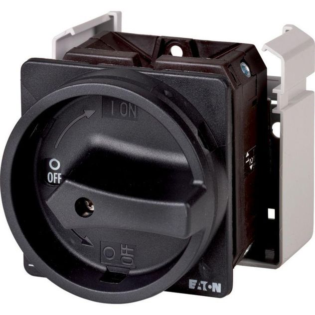
Eaton 207426
Contact us for pricing and availabilityEaton 092229
Contact us for pricing and availability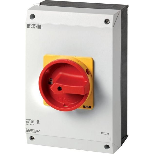
Eaton 255907
$1,150.50Unit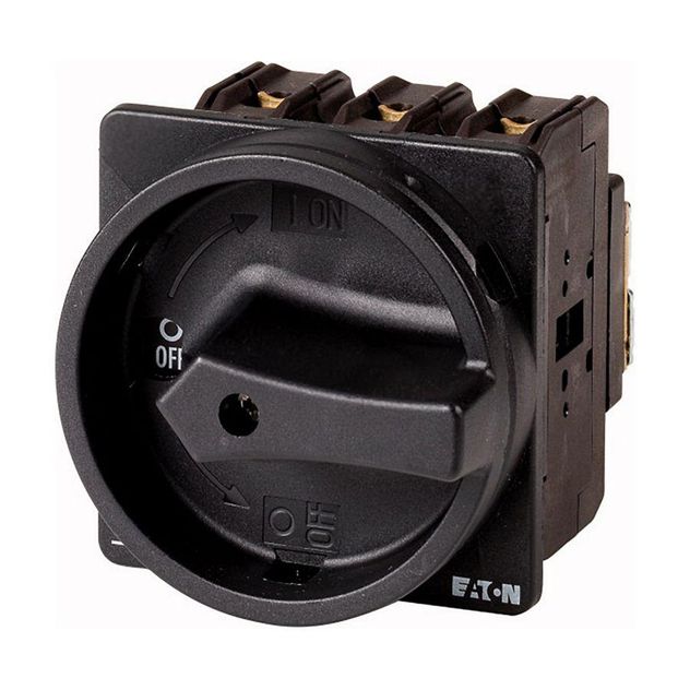
Eaton 069724
$725.60Unit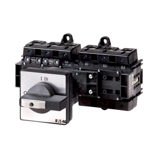
Eaton 200127
Contact us for pricing and availability
Eaton 051806
Contact us for pricing and availability
Eaton 277489
Discontinued - Contact Us For Pricing & Availability
Eaton 277862
Contact us for pricing and availability
Eaton 277553
Discontinued - Contact Us For Pricing & Availability
Eaton 239402
Contact us for pricing and availability
Eaton 239480
Contact us for pricing and availability


