Eaton 052725
SKU: CS5483090MPN: 052725Alternate Part #: MSAA052725UPC/EAN: 4015080527251
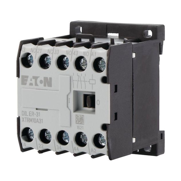
Eaton Moeller® series DILER Control relay


Contact us for pricing and availability
Product Details
Eaton Moeller® series DILER Contactor relay, 230 V 50/60 Hz, N/O \= Normally open: 4 N/O, Screw terminals, AC operation
Attributes
| 10 10 Temperature Rise | The panel builder is responsible for the temperature rise calculation. Eaton will provide heat dissipation data for the devices. |
| 10 11 Short Circuit Rating | Is the panel builder’s responsibility. The specifications for the switchgear must be observed. |
| 10 12 Electromagnetic Compatibility | Is the panel builder’s responsibility. The specifications for the switchgear must be observed. |
| 10 13 Mechanical Function | The device meets the requirements, provided the information in the instruction leaflet (IL) is observed. |
| 10 2 2 Corrosion Resistance | Meets the product standard’s requirements. |
| 10 2 3 1 Verification Of Thermal Stability Of Enclosures | Meets the product standard’s requirements. |
| 10 2 3 2 Verification Of Resistance Of Insulating Materials To Normal Heat | Meets the product standard’s requirements. |
| 10 2 3 3 Resist Of Insul Mat To Abnormal Heat Fire By Internal Elect Effects | Meets the product standard’s requirements. |
| 10 2 4 Resistance To Ultra Violet Uv Radiation | Meets the product standard’s requirements. |
| 10 2 5 Lifting | Does not apply, since the entire switchgear needs to be evaluated. |
| 10 2 6 Mechanical Impact | Does not apply, since the entire switchgear needs to be evaluated. |
| 10 2 7 Inscriptions | Meets the product standard’s requirements. |
| 10 3 Degree Of Protection Of Assemblies | Does not apply, since the entire switchgear needs to be evaluated. |
| 10 4 Clearances And Creepage Distances | Meets the product standard’s requirements. |
| 10 5 Protection Against Electric Shock | Does not apply, since the entire switchgear needs to be evaluated. |
| 10 6 Incorporation Of Switching Devices And Components | Does not apply, since the entire switchgear needs to be evaluated. |
| 10 7 Internal Electrical Circuits And Connections | Is the panel builder’s responsibility. |
| 10 8 Connections For External Conductors | Is the panel builder’s responsibility. |
| 10 9 2 Power Frequency Electric Strength | Is the panel builder’s responsibility. |
| 10 9 3 Impulse Withstand Voltage | Is the panel builder’s responsibility. |
| 10 9 4 Testing Of Enclosures Made Of Insulating Material | Is the panel builder’s responsibility. |
| Ambient Operating Temperature Enclosed Max | 40 CEL |
| Ambient Operating Temperature Enclosed Max Uom | CEL |
| Ambient Operating Temperature Enclosed Min | 25 CEL |
| Ambient Operating Temperature Enclosed Min Uom | CEL |
| Ambient Operating Temperature Max | 50 CEL |
| Ambient Operating Temperature Max Uom | CEL |
| Ambient Operating Temperature Min | -25 CEL |
| Ambient Operating Temperature Min Uom | CEL |
| Application | Contactor relays |
| Climatic Proofing | Damp heat, cyclic, to IEC 60068-2-30 Damp heat, constant, to IEC 60068-2-78 |
| Code Number | 40E |
| Connection Type Auxiliary Circuit | Screw connection |
| Control Circuit Reliability | < 2 λ, < 1 failure at 100,000,000 Operations (at Uₑ = 24 V DC, Umin = 17 V, Imin = 5.4 mA) |
| Conventional Thermal Current Ith At 50 C 3 Pole Open | 10 AMP |
| Conventional Thermal Current Ith At 50 C 3 Pole Open Uom | AMP |
| Degree Of Protection | IP20 |
| Duty Factor | 100 % |
| Equipment Heat Dissipation Current Dependent Pvid | 0 WTT |
| Equipment Heat Dissipation Current Dependent Pvid Uom | WTT |
| Features | Positive operating contacts to EN 60947-5-1 appendix L, including auxiliary contact module |
| Fitted With | Interlocked opposing contacts |
| Heat Dissipation Capacity Pdiss | 0 WTT |
| Heat Dissipation Capacity Pdiss Uom | WTT |
| Heat Dissipation Per Pole Current Dependent Pvid | 0.4 WTT |
| Heat Dissipation Per Pole Current Dependent Pvid Uom | WTT |
| Lifespan Mechanical | 10,000,000 Operations (AC operated) |
| Mounting Method | DIN-rail/screw |
| Mounting Position | As required (except vertical with terminals A1/A2 at the bottom) |
| Number Of Auxiliary Contacts Change Over Contacts | 0.0000 |
| Number Of Auxiliary Contacts Normally Closed Contacts | 0.0000 |
| Number Of Auxiliary Contacts Normally Closed Contacts Delayed Switching | 0.0000 |
| Number Of Auxiliary Contacts Normally Open Contacts | 4.0000 |
| Number Of Auxiliary Contacts Normally Open Contacts Leading | 0.0000 |
| Number Of Contacts Normally Open Contacts | 4.0000 |
| Operating Frequency | 9000 Operations/h |
| Operating Voltage At Ac 50 Hz Max | 500 VLT |
| Operating Voltage At Ac 50 Hz Max Uom | VLT |
| Operating Voltage At Ac 50 Hz Min | 17 VLT |
| Operating Voltage At Ac 50 Hz Min Uom | VLT |
| Operating Voltage At Ac 60 Hz Max | 500 VLT |
| Operating Voltage At Ac 60 Hz Max Uom | VLT |
| Operating Voltage At Ac 60 Hz Min | 17 VLT |
| Operating Voltage At Ac 60 Hz Min Uom | VLT |
| Operating Voltage At Dc Max | 220 VDC |
| Operating Voltage At Dc Max Uom | VDC |
| Operating Voltage At Dc Min | 24 VDC |
| Operating Voltage At Dc Min Uom | VDC |
| Overvoltage Category | III |
| Pick Up Voltage | 0.8 - 1.1 V AC x Uc (voltage tolerance - single-voltage coil 50 Hz and dual-voltage coil 50 Hz, 60 Hz) 0.85 - 1.1 V AC x Uc (voltage tolerance - dual frequency coil 50/60 Hz) |
| Pollution Degree | 3.0000 |
| Power Consumption Sealing 50 Hz | 1.8 W, Dual-frequency coil in a cold state and 1.0 x Us 3.9 VA, Dual-frequency coil in a cold state and 1.0 x Us 5.4 VA, Dual-frequency coil in a cold state and 1.0 x Us |
| Power Consumption Sealing 60 Hz | 1.8 W, Dual-frequency coil in a cold state and 1.0 x Us 3.9 VA, Dual-frequency coil in a cold state and 1.0 x Us 5.4 VA, Dual-frequency coil in a cold state and 1.0 x Us |
| Product Category | DILER Mini-contactors |
| Protection | Finger and back-of-hand proof, Protection against direct contact when actuated from front (EN 50274) |
| Rated Control Supply Voltage Us At Ac 50 Hz Max | 230 VLT |
| Rated Control Supply Voltage Us At Ac 50 Hz Max Uom | VLT |
| Rated Control Supply Voltage Us At Ac 50 Hz Min | 230 VLT |
| Rated Control Supply Voltage Us At Ac 50 Hz Min Uom | VLT |
| Rated Control Supply Voltage Us At Ac 60 Hz Max | 230 VLT |
| Rated Control Supply Voltage Us At Ac 60 Hz Max Uom | VLT |
| Rated Control Supply Voltage Us At Ac 60 Hz Min | 230 VLT |
| Rated Control Supply Voltage Us At Ac 60 Hz Min Uom | VLT |
| Rated Control Supply Voltage Us At Dc Max | 0 VLT |
| Rated Control Supply Voltage Us At Dc Max Uom | VLT |
| Rated Control Supply Voltage Us At Dc Min | 0 VLT |
| Rated Control Supply Voltage Us At Dc Min Uom | VLT |
| Rated Impulse Withstand Voltage Uimp | 6000 V AC |
| Rated Insulation Voltage Ui | 690 VLT |
| Rated Insulation Voltage Ui Uom | VLT |
| Rated Operational Current For Specified Heat Dissipation In | 6 AMP |
| Rated Operational Current For Specified Heat Dissipation In Uom | AMP |
| Rated Operational Current Ie | 2.5 A at 60 V, DC L/R ≤ 15 ms (with 2 contacts in series) 1.5 A at 110 V, DC L/R ≤ 15 ms (with 3 contacts in series) 2.5 A at 24 V, DC L/R ≤ 15 ms (with 1 contact in series) 0.5 A at 220 V, DC L/R ≤ 15 ms (with 3 contacts in series) 10 A |
| Rated Operational Current Ie At Ac 15 220 V 230 V 240 V | 6 AMP |
| Rated Operational Current Ie At Ac 15 220 V 230 V 240 V Uom | AMP |
| Rated Operational Current Ie At Ac 15 380 V 400 V 415 V | 3 AMP |
| Rated Operational Current Ie At Ac 15 380 V 400 V 415 V Uom | AMP |
| Rated Operational Current Ie At Ac 15 500 V | 1.5 AMP |
| Rated Operational Current Ie At Ac 15 500 V Uom | AMP |
| Rated Operational Voltage Ue At Ac Max | 600 VLT |
| Rated Operational Voltage Ue At Ac Max Uom | VLT |
| Rated Switch Current | 10 AMP |
| Rated Switch Current Uom | AMP |
| Safe Isolation | 300 V AC, Between auxiliary contacts, According to EN 61140 300 V AC, Between coil and auxiliary contacts, According to EN 61140 |
| Screw Size | M3.5, Terminal screw |
| Screwdriver Size | 2, Terminal screw, Pozidriv screwdriver 0.8 x 5.5/1 x 6 mm, Terminal screw, Standard screwdriver |
| Shock Resistance | 10 g, N/O auxiliary contact, Basic unit with auxiliary contact module, Mechanical, according to IEC/EN 60068-2-27, Half-sinusoidal shock 10 ms 8 g, N/C auxiliary contact, Basic unit with auxiliary contact module, Mechanical, according to IEC/EN 60068-2-27, Half-sinusoidal shock 10 ms |
| Short Circuit Protection Rating | 10 A fast, 500V, Maximum fuse, Short-circuit rating without welding, Contacts |
| Short Circuit Protection Rating Without Welding | 6 A gG/gL, 500 V, Max. Fuse, Contacts |
| Static Heat Dissipation Non Current Dependent Pvs | 1.8 WTT |
| Static Heat Dissipation Non Current Dependent Pvs Uom | WTT |
| Switching Capacity Auxiliary Contacts General Use | 10 A, 600 V AC, (UL/CSA) 0.5 A, 250 V DC, (UL/CSA) |
| Switching Capacity Auxiliary Contacts Pilot Duty | P300, DC operated (UL/CSA) A600, AC operated (UL/CSA) |
| Switching Time Ac Operated Make Contacts Closing Delay Max | 21 C26 |
| Switching Time Ac Operated Make Contacts Closing Delay Max Uom | C26 |
| Switching Time Ac Operated Make Contacts Closing Delay Min | 14 C26 |
| Switching Time Ac Operated Make Contacts Closing Delay Min Uom | C26 |
| Switching Time Ac Operated Make Contacts Opening Delay Max | 18 C26 |
| Switching Time Ac Operated Make Contacts Opening Delay Max Uom | C26 |
| Switching Time Ac Operated Make Contacts Opening Delay Min | 8 C26 |
| Switching Time Ac Operated Make Contacts Opening Delay Min Uom | C26 |
| Switching Time Ac Operated N O With Auxiliary Contact Module Closing Delay | 45 C26 |
| Switching Time Ac Operated N O With Auxiliary Contact Module Closing Delay Uom | C26 |
| Terminal Capacity Flexible With Ferrule | 1 x (0.75 - 1.5) mm² 2 x (0.75 - 1.5) mm² |
| Terminal Capacity Solid | 1 x (0.75 - 2.5) mm² 2 x (0.75 - 2.5) mm² |
| Terminal Capacity Solid Stranded Awg | 1 x (18 - 14) 2 x (18 - 14) 18 - 14 |
| Voltage Type | AC |
| Voltage Type Of Operating Voltage | AC/DC |
Specifications
| SKU | CS5483090 |
|---|---|
| MPN | 052725 |
| Alternate Part # | MSAA052725 |
| UPC/EAN | 4015080527251 |
You may also like
Eaton 021624
Contact us for pricing and availability
Eaton 051779
Contact us for pricing and availability
Eaton 276400
Contact us for pricing and availability
Eaton 293988
Contact us for pricing and availability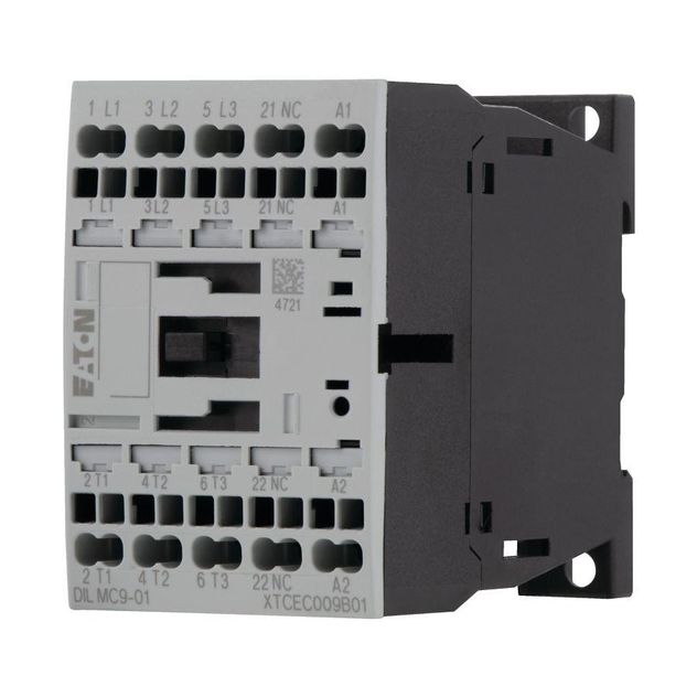
Eaton 277489
Discontinued - Contact Us For Pricing & Availability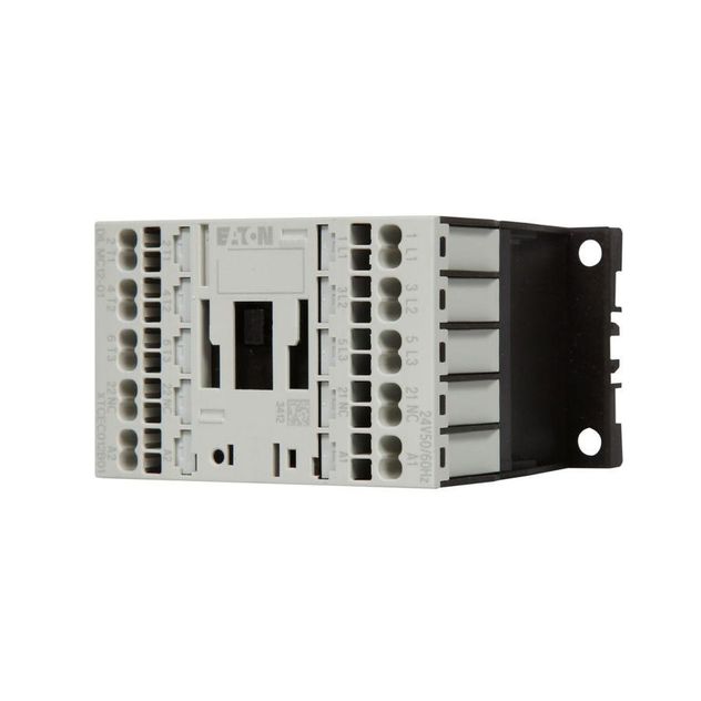
Eaton 277553
Discontinued - Contact Us For Pricing & Availability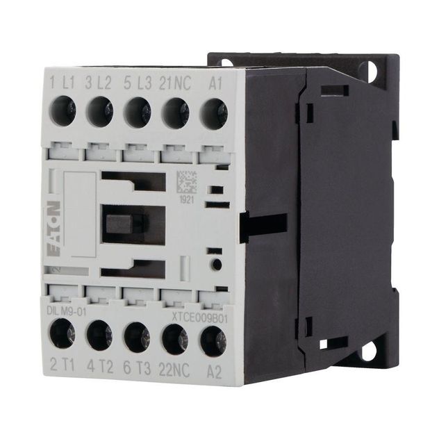
Eaton 276732
Contact us for pricing and availability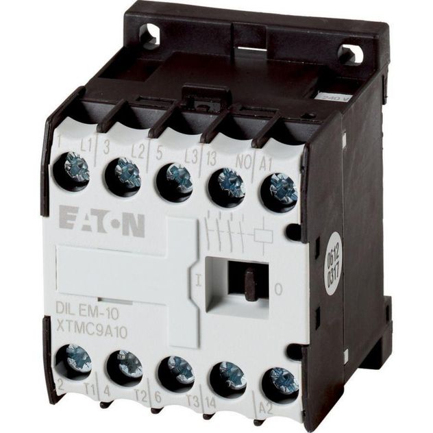
Eaton 021455
Contact us for pricing and availabilityEaton 021520
Contact us for pricing and availability
Eaton 051806
Contact us for pricing and availability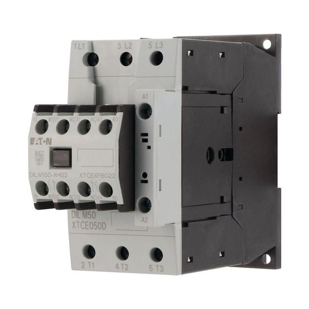
Eaton 277862
Contact us for pricing and availability
Eaton 277833
Contact us for pricing and availability


